

catch basins
The purpose of a catch basin is to collect or catch surface water from a desired area and direct it through an underground system of pipes to an outlet location (ditch, stream, lake, ocean, etc). Catch basins are typically found on most streets, highways, and busy roads. They are most commonly utilized in areas which experience significant storms and floods. Most catch basins and in turn storm drainage systems are engineered to move storm precipitation (non-treated) into larger bodies of water. Another purpose for a catch basin is to trap sediment in the ‘sump’ of the basin so it doesn’t make its way into the piping system clogging pipes.


Area Inlet
Curb Inlet
A majority of common day catch basins are made of steel reinforced or non-reinforced precast concrete, but there are also brick and mortar, plastic, and polymer type catch basins
Brick & Mortar Basin

Plastic/Polymer Basin

Square Precast Concrete Concrete Basin
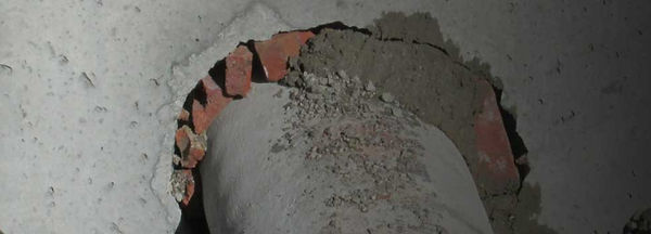
The middle and earlier 20th century was known mostly for brick and mortar catch basins. The typical common day catch basin is made of concrete precast in a plant specializing in such work where their equipment is specifically tailored for precast structures. A precast catch basin is typically formed, cast, cured, and stripped in an indoor controlled environment to maximize strength and performance.
Catch basins can be round or square depending on the use. Round catch basins are more common for receiving larger pipes (24″-60″ or more) at skewed angles. Square catch basins are seen more with smaller pipe diameters (4-24″) which enter the basin relatively perpendicular to the wall of the catch basin.
A catch basin is typically made of 3 pieces: the base, the riser, and the top. But it is not uncommon for a catch basin to be two pieces only, an integral base/riser and a top.

Catch Basin Base & Top with Grate

Area Inlet Square Catch Basin Frame & Grate

A catch basin will typically have a ‘casting’ on top of the basin itself which is essentially a cast iron lid allowing water infiltrations and durable enough to last through weather and traffic for decades before requiring replacement. Catch basins typically receive only a grate made to fit into the preformed recesses of the precast concrete top, but there are frame and grate combos used in conjunction with catch basins, particularly for inlet basins.
Curb Inlet Frame, Grate, & Top Combo
A catch basin will typically have a ‘casting’ on top of the basin itself which is essentially a cast iron lid allowing water infiltrations and durable enough to last through weather and traffic for decades before requiring replacement. Catch basins typically receive only a grate made to fit into the preformed recesses of the precast concrete top, but there are frame and grate combos used in conjunction with catch basins, particularly for inlet basins.

One of the more common types of grates is slotted. The vertical elevation assigned to the bottom of the inside of the inlet and outlet pipe penetration is referred to as the ‘invert’ elevation. The invert elevation is a critical part of the entire drainage system dictating how water will flow, is typically designed by the engineer, and the cored holes must be placed accurately (vertically, horizontally, and at the correct skew) by the precast manufacturer. ‘Shop drawings’ are usually sent to be reviewed by the engineer to assure everything is correct prior to fabrication. The term ‘springline’ refers to the elevation at the center of the pipe.
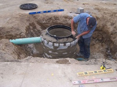
The typical crew required for installing a catch basin consists of 3-4 workers: an operator, 1-2 laborers, and a foreman. The equipment required will be a backhoe or excavator rated to lift the heaviest piece of the catch basin and a front end loader to move and place bedding and backfill material into the excavation.
The hole where the basin will be placed is excavated large enough for the workers to install pipe into the basin. The excavation is then typically bedded with aggregate stone.
The more common aggregate size used for bedding follows the following sieve analysis: 100% passing 1” sieve, 900-100% passing ¾” sieve, 20-55% passing ½” sieve, 0-15% passing 3/8” sieve, 0-5% passing 4.75mm sieve. The purpose of the bedding is to provide a stable working platform, provide a leveling surface, and to provide a subgrade that will not shift or move the structure after installation.


Once the approximate depth is calculated and excavated, the backhoe operator will pick up the catch basin base with chains, slings, or anchor points and slowly lower it into the hole. Care should be taken for the workers to never be underneath a structure piece as it is being lowered into position. Once the base section is in the correct position, the next step is to lower and interlock the riser section onto the base. Lastly the top is lowered and placed above the riser.
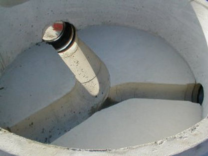
Inlet and outlet pipes connecting to a catch basin can either be grouted closed or booted with a manufactured rubber boot. Seeing that catch basins serve storm water drainage only and groundwater infiltration is not a significant concern, the most common way to close off a pipe penetration into a catch basin is the grout method.
Though in some unique situations, booted connections may be necessary or required by the engineer.

'Inverts' are precast or cast-in-place

Catch Basin with sump
Sometimes the engineer or inspector will require a mastic (typically peel and stick) be placed between pieces (bottom, riser, and top) of a catch basin structure. This helps keep groundwater or drainage seepage water from entering or exiting the basin.
The cored hole (commonly done at the precast plant) into the catch basin is typically slightly larger than the outside diameter of the pipe going in, to allow a little ‘give’ in installing the pipe appropriately.
At the bottom of most catch basins will be a feature also called an ‘invert’ which is a precast or cast in place concrete or grout which is formed to the flow of the water passing through the catch basin. The purpose of the invert is essentially the opposite of a trapping ‘sump’ to help in the flow of water and to keep sediment flowing with the stream rather than being caught in the ‘trap’ of a sump. Sometimes a sump is required which is essentially additional catch basin depth below the lowest pipe invert which traps and sumps water and debris.

Also something referred to as a ‘grade ring’ is commonly installed between the top of the precast basin and the casting. Essentially the function of a grade ring is to allow final minor adjustments in the elevation of the casting upon established the finish grade which will surround the casting. Grade rings typically come from 1” to 6” thick and can be circular or square in shape. There is usually a limit placed by engineers on the amount of grade rings that can be installed before an actual riser section will be required. A common rule of thumb is a maximum of 12”. It is typically required that mastic be installed between each grade ring.


Once the final elevation has been achieved and the catch basin is permanently set in place horizontally and vertically, the excavated area surrounding the catch basin is backfilled. The worker will then grout or ‘mud’ closed the area or joint on the inside of the catch basin between the bottom of the casting and the top of the riser. This is the final step of closing off the basin from water infiltration or exfiltration.
Lastly, depending on whether the catch basin is within an area with vehicle traffic, a ‘concrete collar’ may be required. This is typically the last task done when installing a catch basin. A concrete collar is a cast in place concrete section formed and poured around the casting giving additional strength and reinforcement to the catch basin from vehicle traffic. The concrete collar also helps resist the entire assembly from shifting or moving with vehicle traffic or freeze thaw conditions.
