horizontal directional drilling
For utilities (electric, water, sanitary, storm, gas) that need to pass cross under pavements, streams, and and railroad tracks, engineers will often specify they be bored or drilled underneath of. This is referred to as trenchless technology or Directional Drilling/Boring. The word directional indicates the drillers ability to aim the drill’s line and grade. With pressure pipe or electrical conduit/wire, the line and grade is only restricted to the drill’s ability. With gravity pipe (storm and sanitary sewer), line and grade must be planned and accounted for to assure the proper slope is achieved. A general rule-of-thumb for estimating maximum radius for changes in line or grade is commonly pipe diameter times 40 for plastic pipe, and pipe diameter times 100 for steel/iron pipe.
The size of the pipe will often dictate the drilling rig power required, the bigger the pipe the larger the rig. Also soil type and soil density will factor into the efficiency of the drilling. Engine horsepower, thrust, and pull back will factor into efficiency as well, among other specifications of the rig’s engine.


The directional drilling process involves the following: First the max deflection capability angle of the drill must be taken into account with respect to the total depth of the anticipated drill. This will dictate how much length must exist between the entrance pit and the exit pit. If Site features or other factors restrict ideal pit placement location, the pits may have to be closer together to allow for a greater initial drill depth to achieve safe clearance underneath the item that’s being drilled under.
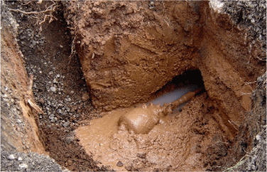
An entrance pit must be excavated for the placement of the machine. This pit is typically constructed with an entrance ramp (for larger machines or deeper pits) with dimensions that will suit the size of the boring machine and additional perimeter room for laborers and operators. The pit depth is often based on the size of the machine and the anticipated drill operations situational and dimensional restraints.

Though all machines and company’s policies are different, a typical rule of thumb for a industrial grade drilling machine capable of up to 24″ diameter pipe is:
-It can be expected to achieve 18″ of vertical movement downward with a 15′ drill rod passing through standard soil conditions. This constitutes a max 10 degree drilling angle with 5-8 degrees being the more moderate operating ranges for such a situation.
-For large diameter and deep bores, the entrance pit bottom is usually lined with aggregate stone to improve the terrain conditions for the machine and foot traffic. Then the machine is placed appropriately in the pit and the boring operation begins.
First a pilot hole is drilled along the correct line and grade to set the alignment of the bore. The drilling head is typically located from the surface with use of a walkover system (beacon signal sent out from the drill head monitored from the surface). Also electromagnetic navigation systems are also available for monitoring the line and grade during the boring process.


The pilot hole is found in the receiving pit
The pilot bit is removed and a back reamer bit is installed, larger than the outside diameter of the pipe to be pulled back the other direction.
Sometimes for larger diameter pipe or stubborn soils, there are several reaming operations each one using a larger reamer until the correct size horiontal drilled shaft is present to pull the final pipe into it's final resting place.
The final horizontal drilled shaft must be big enough to smoothly accept the final pipe, but not so large that an excessively large annular space exists, which can lead to settlement at grade or excessively settling/movement after the final pipe is pulled into place

On the back-reamer assembly, included is a pipe clamp or grasping mechanism on with the permanent or 'carrier' pipe is attached.


Then back reamer cutter is passed through enlarging the pilot hole diameter while carrying the ‘carrier’ pipe with it on a swivel. This is all done with the help of drilling fluid which is typically made of water and bentonite or polymer. The drilling fluid is pumped into the drilling head to help remove the spoils, stabilize the hole, cool the cutting head, and lubricate the pipe.

The carrier pipe then passes through a receiving pit dug at the opposite end of the run, from which another drilling operation may begin or an open cut trench installation can commence.

