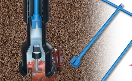
water main gate valves
A gate valve is the most common type of in-line valve used for opening and closing the flow of water in a water main. Gate Valves come in many different sizes depending on the watermain they are being attached to. The primary purpose of a mainline gate valve is for shutting off or ‘isolating’ certain sections of watermain to allow for work or maintenance of the waterline system without water gushing out everywhere.
A gate valve can be installed in two conditions, one is on a new or proposed water main and the other is tapped on to a live water main (nearest valves are shut off on either side). This description addresses a standard mainline gate valve which is most often installed as the new water main is installed.
A gate valve consists of 2 flanged ends where the water main will butt up to and bolt on with a joint restraint system (often a megalug). Above the 2 flanged ends is the valve chamber and a bonnet bolt/nut on the top which is present to open or close the valve with a wrench.


On top of the bonnet bolt/nut sits a valve box which will protect the valve nut from backfill operations, allow future location of the gate valve from above grade, and provides a clean and straight path for a wrench.
There are many different types of valve boxes meant for mainline gate valves and curb stop service valves. The more common types are sliding or screw type with standard or locking lids. The assembly is most commonly three or four piece; base, riser, extension (if needed) and lid. A valve wrench or ‘key’ is used through the valve box shaft to turn the valve on and off.


Gate valves are also commonly placed inside a precast manhole, often ‘doghoused’ to be placed over the water main.
The typical crew required for mainline gate valve installation will be an operator and 2 pipe laborers. 1-2 pipe laborers will stand in the trench and receive the gate valve assembly from the backhoe by way of ropes/chains/slings etc. The gate valve will be suspended in place until the pipe laborers establish the attachment bolts with enough support for the valve to be freestanding. Then the bolts are tightened further until the manufacturer or engineers specified torque strength has been reached.

