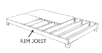
wood joist floor assembly
A wood joist floor system provides a spanning, level platform assembly for the floor which is an integral part of the building structure. The wood joist and subfloor assembly provides a structural diaphram that transfers loads to the shear walls. As a wood floor system is combustible, the finish floor materials will determine the actual fire rating. Standard floor joists are commonly spaced 12″, 16″, or 24″ on-center depending on the applied load, subfloor thickness and spanning capacity, species of lumber, and allowable defection by code.
A vertical rim joist is installed around the perimeter of the room, often nailed to a pressure treated sill plate below, which receives (often 2×6 or 2×8) perpendicular joists.

To provide lateral support, end joists are sometimes doubled with the RIM joist running paralell for additional floor strength and support if a wall will be framed above. Joists can be supported by wood stud framing, steel beams, wood beams, concrete, or masonry. Minimum bearings for joists are commonly 1-1/2″ on wood and 3″ on concrete or masonry. The common span length typically allowed for different joists sizes is the following:
2×6: 0-10′
2×8: 8-12′
2×10: 10-14′
2×12: 12-18′
A common rule of thumb for choosing proper joist depth is anticipated Span/16. Joist deflection should not exceed 1/360 of the span. If depth of joist is not a concern, deeper joists spaced farther apart is typically most desirable. Bridging is sometimes utilized which keeps joists from turning and bending. Bridging is wood or metal crossbracing, placed diagonal or perpendicular which may be required by code particularly when joist depth is more than 6 times it’s thickness, but typically it’s not necessary if the joist ends are appropriately laterally supported and the joists tops will be attached to the subfloor.


Another common rule of thumb for plumbing or electrical runs that need to pass through the joists perpendicular is:
– no diameters larger than 1/3 joist depth
– no penetrations within 1/6 joist depth from top or bottom
– no penetrations within middle 1/3 of span.

Sill plate anchors or hold-downs may be required to secure wall/floor from wind or seismic loads.

Joists are typically attached to a RIM joist with 16d nails through the outside of the RIM joist. The RIM joist will be nailed to the sill plate. The joists are also toe nailed to the sill plate with 8d nails every 16″ on-center. Sill plates are typically set back slightly to receive wall sheathing which rests on the foundation. Sill sealer is commonly placed between the sill plate and the foundation to keep moisture, insects, air, etc from passing through. 1/2″ anchor bolts are commonly placed every 6′ on-center, minimum 2 bolts per sill piece, and at least 12″ from each end. A sill plate may be doubled for stiffness, which is nailed with 10d nails, staggered every 24″ and lapped at corners.
The following are some load-bearing and non-load-bearing wall conditions as they relate to floor joist framing and placement:

Non-bearing partitions paralell to the joist (with no partition below) require no reinforcement framing below.
Non-bearing partitions parallel and in-between the joists (with no partition below) will typically require solid blocking (with or without ledgers) perpendicular every 16″ on-center in between joists.


If a bearing partition perpendicular to joists rests on top of a joist below, the joist will commonly need to be doubled and with double plates below, with possible need for columns
If a bearing partition is being placed below and perpendicular to floor joists (with no partition above) perpendicular blocking may be required between the joists


If a non-bearing partition is being placed below, parralel to, and in-between the joists, perpendicular joists blocking will commonly be required
Floor projections, openings, and irregular situations require custom framing configurations designed by a qualified engineer


Floor openings will require additional framing member reinforcing configurations
